 .pdf
.pdf
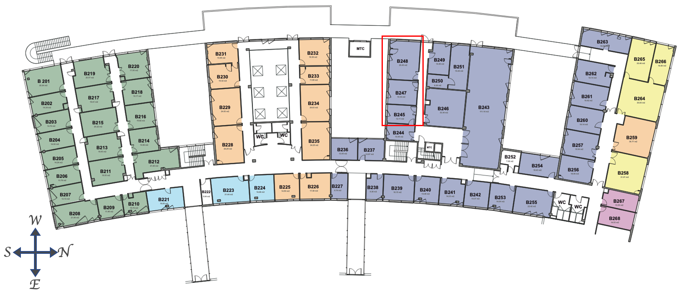
Three rooms model
| This test case is derived from API-B building . The study is limited to three rooms of the second floor: two offices (B245 and B247) and a meeting room (B248). |
1. Geometry
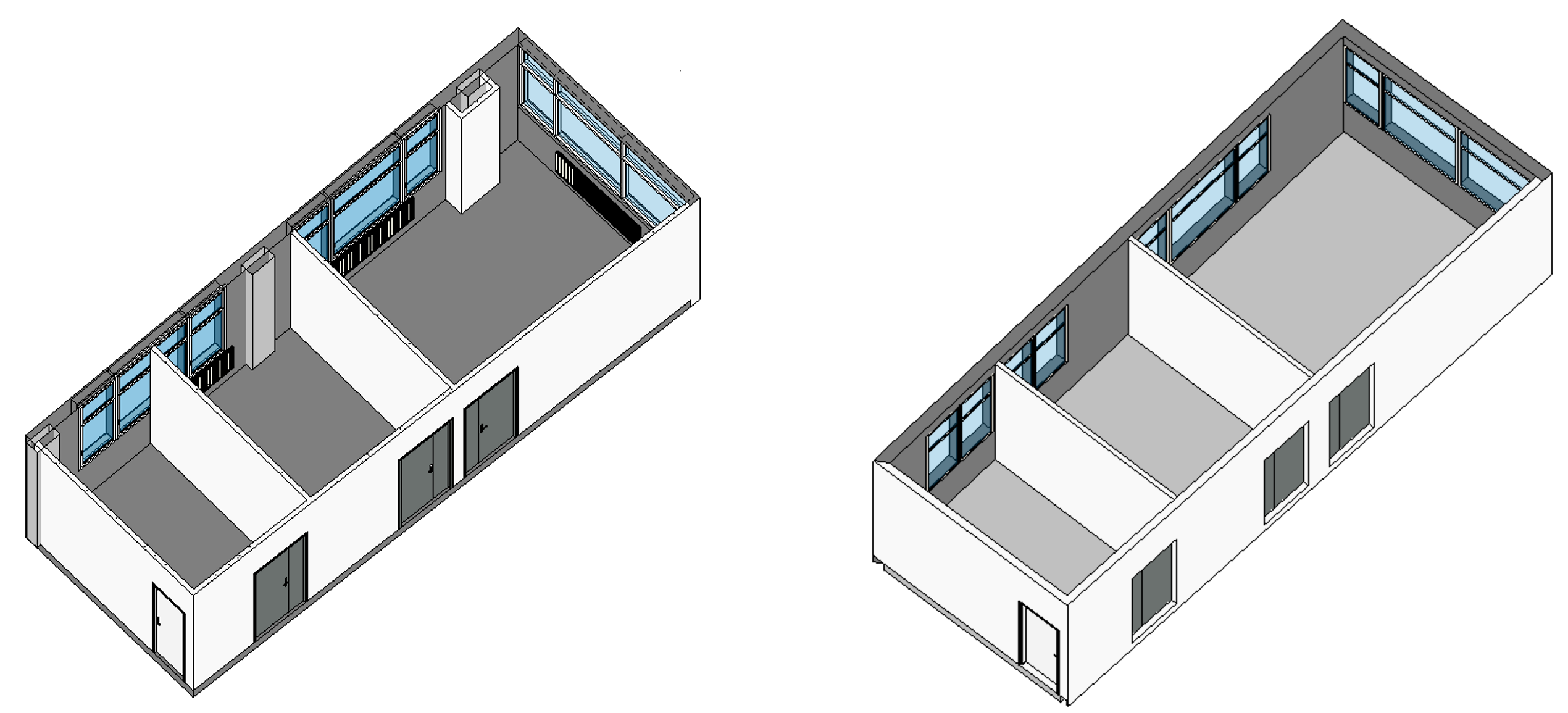
To generate the corresponding thermal model using ktirio service, the first step is to create a simplified geometry using a CAD software and export it in ifc format. In our case, we used Revit software to create the digital mockup of the building from a 3D scan (point cloud). The resulting model is shown in Figure 2. One can notice that several details were deleted. Indeed, only the components that are involved in the description of the building envelope are kept.
2. Energy systems and equipments
During the heating period, the studied three rooms are heated thanks to three convectors: one in B247 and two in B248 (see Figure 2). They are operated by the building manager but their power can be individually set up by manual valves. The air renewal in insured by a simple flow ventilation.
3. Model configuration
As a first approach, the three rooms are considered as a single building which all outside walls and slabs are in contact with the outside air. The thermal properties of the envelope components are set as shown in Table 1. The unknown thermal properties such as the glazing solar factor are set to default values. We consider a constant air renewal rate of \(0.5 \text{vol}/\text{h}\). We fix the heating set temperature at \(\text{TSetH} = 293.15 \text{K}\) and the cooling set temperature at \(\text{TSetC} = 299.15 \text{K}\) and we calculate the ideal heating and cooling loads for a 15 day period (from 2021/01/27 to 2021/02/10). The weather data is taken from meteoblue.com for the same period.
Walls |
Material |
Thickness(m) |
U \((\text{W}.\text{m}^{-2}.\text{K}^{-1})\) |
Density \((\text{kg}/\text{m}^3)\) |
Thermal capacity \((\text{J}/\text{kg}.\text{K})\) |
Internal walls |
Plaster |
0.10 |
9.10 |
850 |
2300 |
External walls |
Concrete |
0.26 |
0.45 |
800 |
100 |
Ceiling, floor |
Concrete |
0.30 |
0.90 |
850 |
2300 |